Table of Contents
Categories
-
Adapter Sleeves (9)
-
Ball Bearings (11)
-
Ball Screw Bearings (2)
-
Ceramic Bearings (28)
-
Pillow Block Bearings (4)
-
Plain Bearings (32)
-
Roller Bearings (12)
-
Slewing Bearings (43)
-
Sliding Block (3)
-
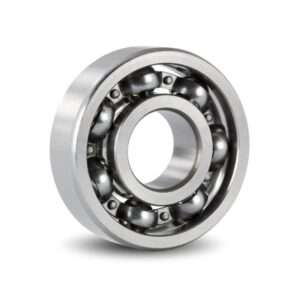
Stainless Steel Bearings (27)
-
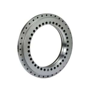
Super Precision Bearings (6)
-
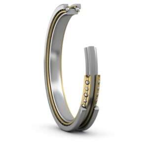
Thin Section Bearings (9)
-
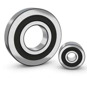
Track Rollers (4)
-
Universal Joints (1)


Cylindrical Roller Bearings: NU vs NJ vs NUP

Cylindrical roller bearings in standard single-row NU designs accommodate axial displacement in both directions, NJ designs locate a shaft in one direction, and NUP designs locate it in both directions. The difference comes from the inner-ring ribs: NU has none, NJ has one, and NUP has one integral rib plus a separate loose flange ring. Choose among them from the shaft's locating and thermal-expansion requirements, then verify axial capacity, allowable travel, lubrication, and retention for the exact bearing.
1. Start with the Shaft's Axial Function
1.1 What NU, NJ and NUP Tell You
The prefix identifies how the bearing's ribs control relative axial movement between its rings. In the standard designs compared here, NU provides internal axial freedom, NJ provides one-direction location, and NUP provides two-direction location. NTN's cylindrical roller bearing catalog shows these arrangements and distinguishes floating-side from fixed-side use. Start with that function before comparing prices or selecting a familiar size.
1.2 The Scope of This Comparison
This guide compares standard single-row NU, NJ, and NUP configurations. Double-row, full-complement, precision spindle, and cylindrical roller thrust bearings require their own selection review. Similar dimensions do not establish equal axial behavior, cage construction, or load capacity. Use FHD's cylindrical roller bearing product page to begin an inquiry, then confirm the exact configuration on the proposed drawing.
1.3 Read the Whole Bearing Arrangement
Mark the shaft, housing, bearing positions, and axial force directions on an assembly sketch. Identify which support establishes the shaft's axial position and where thermal movement is intended to occur. Include shoulders, spacers, covers, and retaining hardware that affect the load path. The bearing prefix becomes useful when it is tied to this complete arrangement rather than considered as a standalone purchasing code.
2. NU Bearings: Internal Movement in Both Directions
2.1 Two Outer-Ring Ribs and No Inner-Ring Ribs
A standard NU bearing has two ribs on the outer ring and no ribs on the inner ring. The outer ring guides the roller assembly while the inner ring provides a raceway without an integral axial stop. This construction lets the rings move axially relative to one another within the permitted travel. Do not confuse this internal movement with a loose fit between a ring and its shaft or housing.
2.2 Check the Available Axial Travel
The allowed displacement is a model-specific dimension, not unlimited freedom along the shaft. Compare the required hot-to-cold movement with the manufacturer's allowable travel and the bearing's installed position. An assembly that begins near one travel limit may have too little movement available in the other direction. Specify the assembly reference position and ask how the supplier expects the bearing to remain within its permitted travel throughout operation.
2.3 Assign Axial Load to Another Support
NU is used for radial support where another part of the arrangement provides axial location. Retaining its rings on the shaft and in the housing does not turn its internal geometry into a thrust-supporting design. Show the separate locating bearing or other approved axial support on the drawing. If the application needs this bearing position to react an external axial load, revisit the design rather than assuming the mounting hardware solves that requirement.
3. NJ Bearings: Location in One Direction
3.1 One Inner-Ring Rib Defines the Locating Side
An NJ bearing has two outer-ring ribs and one integral inner-ring rib. That inner rib provides axial location in one direction, while relative displacement remains possible in the other direction within the design limits. The load direction must be described relative to the actual installed orientation. A purchase description that says only NJ leaves the machine builder responsible for placing the rib on the correct side.
3.2 Account for Reversing Axial Forces
Draw both axial force directions when a drive reverses or the process changes its thrust direction. Determine which force the NJ bearing must react and where the opposite force will be supported. NSK's cylindrical roller bearing design overview identifies limited one-direction axial loading for NJ rather than a complete solution for alternating thrust. Ask for a review of the complete bearing arrangement when axial load changes direction during the duty cycle.
3.3 Review Opposed Arrangements as a System
Two appropriately arranged bearings may provide location through opposing one-direction load paths. Their orientation, spacing, axial setting, and retention must be specified together. Installing two NJ bearings does not automatically produce the same behavior as one NUP bearing or guarantee a suitable thermal arrangement. Obtain the machine designer's approval of the complete support system before accepting such an alternative.
4. NUP Bearings: Location in Both Directions
4.1 Identify the Separate Loose Flange Ring
A standard NUP bearing has two outer-ring ribs and one integral inner-ring rib. A separate loose flange ring completes the opposite inner-ring side. That component is part of the bearing's locating construction, not a sealing washer or a disposable packing piece. Keep it identified with the supplied bearing and inspect the assembly drawing before installation.
4.2 Two-Direction Location Needs a Capacity Check
With the required components correctly installed and retained, NUP provides axial location in both directions. The permissible axial load still depends on the exact design and operating conditions. Load magnitude, speed, lubrication, and roller-end contact conditions belong in that review. Do not equate two-direction location with unlimited thrust capacity or treat a radial load rating as an axial rating.
4.3 Fix the Inner-Ring Assembly Axially
The loose flange ring needs the intended axial seating and retention for the load path to work. Follow the bearing supplier's installation drawing and the machine's approved shoulder and retaining-hardware arrangement. Merely placing the ring on the shaft does not demonstrate that the assembly can react thrust safely. Verify the complete inner-ring assembly is fixed axially as specified before checking its two-direction locating function.
5. NU vs NJ vs NUP: A Buyer Comparison
5.1 Compare Ribs, Movement and Location
The table below summarizes the three standard arrangements. Its purpose is to identify the required shaft function before checking a particular bearing's dimensions and ratings. Read axial freedom and axial location as different characteristics, because a locating bearing is not also a bidirectional floating support. Use the manufacturer's drawing whenever an accessory ring, special construction, or additional suffix changes the supplied design.
| Design | Outer-ring ribs | Inner-ring construction | Internal axial movement / location | Selection and assembly check |
|---|---|---|---|---|
| NU | 2 integral ribs | No ribs | Relative displacement in both directions within the model's permitted travel; radial support without bearing-provided axial location | Confirm travel, installed reference position and the separate axial locating support. |
| NJ | 2 integral ribs | 1 integral rib | Location in one direction; relative displacement in the other direction within design limits | Confirm installation orientation, one-direction axial capacity and the opposite load path. |
| NUP | 2 integral ribs | 1 integral rib plus 1 separate loose flange ring | Location in both directions; not a bidirectional floating support | Confirm permissible axial load and specified axial fixing of the inner ring and loose flange assembly. |
5.2 Keep Alternatives Visible in the Quotation
Ask the supplier to name the exact prefix and complete designation offered. If an NJ or NUP alternative is proposed for an NU request, require an explanation of its effect on axial movement and shaft location. The exception should appear in the quotation and marked drawing rather than remain buried in a cross-reference list. Purchasing can then obtain technical approval before comparing the commercial terms.
5.3 Choose from the Movement Requirement
For radial support with thermal movement in both directions, an NU configuration may fit the intended non-locating role. When one axial direction must be located, review NJ and the support for the opposite direction. For two-direction location, review NUP together with its axial capacity and loose-ring retention. The final choice must also satisfy the load, speed, clearance, and mounting requirements of the machine.
6. Locating and Non-Locating Bearing Arrangements
6.1 Give Axial Location a Defined Load Path
Identify how an axial force travels from the shaft through the bearing components into the housing. The locating support and its shoulders or retainers need to carry that reaction as a complete assembly. A layout with unintended location at multiple supports can resist thermal growth and create additional internal loading. Mark any deliberate axial setting or movement feature clearly so assembly staff can distinguish it from an installation error.
6.2 Allow for Shaft and Housing Thermal Growth
A shaft and its housing can change length by different amounts during operation. The resulting movement depends on geometry, materials, and temperatures at the actual supports. An NU bearing accommodates the intended relative displacement internally, so the required movement must fit within its available travel. Have engineering calculate that movement and specify the installed position used to check both operating extremes.
6.3 Separate Axial Endplay from Radial Clearance
Axial endplay describes movement along the shaft, while radial internal clearance concerns movement across it. A radial clearance suffix does not specify the arrangement's axial setting. Record each requirement separately, with its measurement condition and acceptance limit. This distinction prevents a quotation for increased radial clearance from being mistaken for a solution to missing thermal travel or incorrect shaft location.
7. Loads and Ratings for the Selected Design
7.1 Establish Radial Loads and Duty
Give the supplier radial loads at normal operation, startup, shutdown, and any credible overload. Include their duration and the bearing spacing used to calculate reactions. Check the exact model's dynamic and static ratings against the relevant selection method, because those ratings describe different conditions. A bearing's ability to carry substantial radial load does not establish its suitability for every shock, speed, or life requirement.
7.2 Request a Separate Axial-Load Review
For NJ and NUP, supply the axial force, its direction, and how long it acts. Include simultaneous radial loading and the speed and lubricant conditions at that time. Ask the supplier to identify the permissible axial load and the assumptions used to establish it. If thrust dominates the application, the review may require another bearing arrangement rather than a larger cylindrical roller bearing selected only by radial capacity.
7.3 Check Low-Load Operation as Well as Peaks
A bearing selected for the maximum load may spend much of its life under a light load. SKF's low-load testing illustrates why the exact design needs a minimum-load review, particularly as speed changes. Request the manufacturer's minimum-load guidance for the exact model and evaluate idle running, acceleration, and unloaded cycles. Do not add preload or choose a different clearance class as a generic remedy without reviewing the application.
8. Speed, Lubrication and Heat
8.1 Use the Exact Configuration's Speed Data
Specify normal and maximum speed, the time spent at each, and whether axial load is present. A catalog speed figure applies within its stated conditions and may use a reference-speed or limiting-speed definition. Check cage type, lubrication method, clearance, cooling, and any other qualification attached to that figure. Treat changes to the supplied configuration as a reason to revisit the selection rather than retain the original speed assumption automatically.
8.2 Describe the Lubricant and Supply Method
State whether the bearing receives grease, an oil bath, circulating oil, or another defined supply method. Provide the lubricant designation and the temperatures used for selection. NTN's lubrication guidance explains why method and viscosity depend on operating conditions. Ask for a proposal that addresses the raceway and, where axial load is carried, the roller-end and rib contact conditions.
8.3 Make Maintenance Practical
Show how lubricant reaches the bearing and how contamination is controlled. Include replenishment access, filters where applicable, and the existing maintenance procedure. Record any planned lubricant change so compatibility and cleaning can be reviewed before the products are mixed. An agreed maintenance plan should identify the conditions that justify its intervals and the observations that would trigger corrective work.
9. Fits, Retention and Separable Mounting
9.1 Provide the Shaft and Housing Requirements
Send seat dimensions, tolerance limits, materials, and the load direction relative to each ring. NSK's guide to fits and internal clearance explains how mating fits affect bearing operation. FHD's related article on bearing tolerances and performance can help organize the drawing discussion. Select the actual fit for the application rather than applying one shaft-and-housing combination to every NU, NJ, or NUP bearing.
9.2 Review Shoulders and Retaining Hardware
Show the shoulders, fillets, spacers, nuts, covers, and other components that position the rings. Check corner clearance and shoulder contact against the bearing supplier's drawing. For a locating support, the retaining arrangement must sustain the intended axial reaction as well as hold parts during assembly. Agree on the assembly method and hardware settings without inventing a universal tightening value for an unspecified design.
9.3 Handle Separable Components Correctly
These standard designs allow bearing components to be separated for mounting. Use the supplier's instructions to identify which ring and roller assembly can be installed separately. Apply installation force to the appropriate fitted ring and protect raceways and roller ends during reassembly. Keep mating components identified together unless the manufacturer explicitly confirms the permitted interchangeability.
10. Radial Internal Clearance and Axial Setting
10.1 Define the Clearance Measurement Condition
Specify whether the required radial clearance is measured before mounting, after mounting, or under operating conditions. Interference and temperature differences can alter the clearance present in the running bearing. FHD's bearing clearance article is additional background; the exact rolling-bearing requirement should come from the model data and approved drawing. Include the measurement method so incoming inspection and engineering review refer to the same quantity.
10.2 Do Not Select C3 by Habit
A larger-clearance designation is a design choice that needs a reason. Share the fits, expected temperature differences, loads, and operating speed before asking the supplier to recommend a class. Excess clearance can affect running behavior, while insufficient operating clearance can increase internal loading and heat. Approve the recommendation for the actual model and arrangement instead of treating C3 as a universal industrial upgrade.
10.3 Set Axial Position without Unplanned Preload
Document the intended axial setting for a locating bearing or an opposed arrangement. Include spacer dimensions, shoulder positions, and the assembly condition in which the setting is checked. Excessive clamping or incorrect component placement can create an unintended condition even when the bearing designation is correct. Any specified preload needs a defined design basis and verification method; it should not be introduced through guesswork during installation.
11. Alignment, Deflection and Housing Stiffness
11.1 Assess Misalignment at the Bearing
Provide the expected shaft deflection and any relative tilt between the bearing seats. NTN's cylindrical bearing guidance explains that misalignment can concentrate load near roller edges. Manufacturer allowances vary with the design, load, and locating arrangement. Ask for the exact model's assessment rather than quoting one permissible angle for the whole bearing family.
11.2 Inspect the Support Geometry
Check seat roundness, alignment, shoulder squareness, and the support conditions that affect housing deformation. A split or thin-walled housing may behave differently after bolts are tightened or operating load is applied. Identify the relevant datums and inspection condition on the assembly drawing. Correcting the surrounding geometry may be necessary even when the bearing itself passes every dimensional check.
11.3 Review the Bearing Type When Conditions Change
If the machine cannot maintain the required alignment, bring that constraint into the selection review. Another bearing type or a redesigned support may be more suitable, depending on loads, speed, and available space. Preserve the intended locating and non-locating functions when evaluating an alternative. A component substitution cannot be approved from misalignment capability alone while the rest of the shaft arrangement remains unchecked.
12. Cages, Suffixes and Dimensional Interchangeability
12.1 Confirm Cage Construction
Confirm the cage material and construction for the quoted NU, NJ, or NUP model. Steel, brass, and polymer cages need review against their own temperature, lubricant, and speed requirements. SKF's comparison of caged and full-complement designs explains how roller-to-roller contact in conventional full-complement bearings can add sliding, friction, and heat. A full-complement alternative therefore requires a separate review of its exact internal design and operating limits. Similar boundary dimensions do not establish the same capacity, speed capability, or mounting procedure.
12.2 Verify More than Bore, Diameter and Width
Matching bore, outside diameter, and width is only the first part of a replacement check. Compare ribs, corner dimensions, shoulder requirements, roller construction, clearance, cage, and published ratings. Two designs with the same boundary dimensions can require different supporting geometry or offer different performance. Record the full approved designation so future orders do not lose those distinctions.
12.3 Control Rings and Accessories as a Set
Keep the NUP loose flange ring and other required accessories associated with their approved bearing configuration. Separability for mounting does not authorize mixing random rings or roller assemblies from different products. Ask the manufacturer whether replacement components are interchangeable and how they must be identified. Retain that answer in the service documentation, especially when parts may be separated during maintenance.
13. RFQ Information for NU, NJ and NUP
13.1 Describe the Required Bearing Role
Lead the RFQ with the required locating function and attach the shaft arrangement. State the axial force directions, required internal movement, and which support carries the opposite reaction where applicable. Give operating temperatures and the installed reference position used to assess thermal travel. The checklist below keeps these functional inputs separate from the part-number request.
| Input | Buyer entry | Requested supplier confirmation |
|---|---|---|
| Bearing role | [NU floating / NJ one-direction locating / NUP two-direction locating; attach arrangement] | Exact construction and intended shaft function |
| Axial load and movement | [Force directions and duty; hot/cold travel and reference position] | Permissible axial load, available travel and retention assumptions |
| Radial loading and speed | [Normal/peak/minimum load, speed cycle and operating hours] | Exact-model ratings, low-load guidance and selection basis |
| Interfaces and setting | [Shaft/housing dimensions, tolerances, shoulders, materials and assembly] | Fits, clearance and any required geometry changes |
| Product configuration | [Full designation, cage, accuracy, materials and accessories] | Complete offered specification and technical exceptions |
| Lubrication and environment | [Method, lubricant, temperatures, contamination and maintenance] | Applicable operating conditions and maintenance assumptions |
| Acceptance evidence | [Critical dimensions, inspection methods, reports and functional trial] | Sample plan, pass/fail criteria and documentation scope |
| Order stages | [Samples, production quantity, forecast, destination and arrival date] | Unit/one-time costs, minimum quantity and defined lead-time milestones |
13.2 Define the Product and Commercial Scope
Supply the existing full designation or the proposed dimensions, cage, clearance, accuracy, and material requirements. Identify which items are mandatory and which the supplier may propose differently. Add sample quantities, production releases, forecast demand, destination, and the required arrival date. Ask the quote to separate unit price from development or special inspection charges and to show any technical exception.
13.3 Request an Application-Based Selection Response
Provide radial and axial duty, speed changes, environmental exposure, lubrication, and the required service-life basis. Ask the supplier to return the exact proposed configuration with the capacity, travel, and mounting assumptions relevant to that duty. An estimate based on incomplete data should identify the open questions and who will resolve them. Close those questions before the proposal becomes an approved production specification.
14. Incoming Inspection and Application Acceptance
14.1 Match the Delivered Design to the Order
Check the complete designation, drawing revision, ring arrangement, cage, and required accessory components. Verify critical dimensions using the agreed measurement method and acceptance limits. Link the inspection record to the samples or batch received so an issue can be traced to the delivered parts. Use the approval checklist below to distinguish a completed check from a requirement that still awaits evidence.
| Check | Requirement to define | Evidence to retain |
|---|---|---|
| Identity and construction | Full designation, drawing revision, ribs, cage, clearance and accessories | Recorded inspection tied to the supplied samples/batch |
| Interfaces | Critical dimensions, corner clearance, seating and retention | Measured results and approved assembly drawing |
| Axial function | NU travel / NJ orientation / NUP loose flange and axial fixing | Defined assembly check, with remaining functional tests identified |
| Operating trial | Load/speed/temperature duty, lubricant and acceptance characteristics | Test record, deviations and engineering disposition |
| Production release | Resolved exceptions and controlled repeat-order configuration | Written approval, purchase reference and change-control record |
14.2 Verify the Intended Axial Function
Inspect an NJ bearing's orientation against the assembly drawing. For NUP, confirm the loose flange ring is present, seated correctly, and included in the specified axial retention arrangement. For NU, verify that the intended internal travel remains available in the assembled support. Carry out the agreed checks under defined conditions without assuming that free movement by hand proves loaded operating performance.
14.3 Validate the Complete Machine Arrangement
Run the approved trial with the intended lubricant, loads, speeds, and assembly procedure. Record temperature behavior, vibration, noise, positioning, and axial movement where those are acceptance characteristics. Include thermal transitions and reversing forces that matter to the actual duty. Release the design after the specified criteria are met and the remaining exceptions have been resolved by the responsible engineer.
15. Replacement Orders and Quote Review
15.1 Preserve the Original Shaft Function
When replacing a bearing, document how the original arrangement located the shaft and accommodated growth. Inspect the existing designation and supporting parts before concluding that a prefix change is acceptable. A move from NU to NUP, for example, can add axial location where the machine expected movement. Treat a functional change as an engineering revision, even if the replacement slides into the same dimensional space.
15.2 Compare Complete Supply Offers
Review quotations against one controlled requirement sheet and drawing revision. Confirm that loose flange rings, required documentation, packaging, and agreed inspection are included where applicable. Identify minimum quantities, price breaks, quotation validity, and the event that starts the stated lead time. Compare the complete approved supply scope before evaluating the apparent saving in piece price.
15.3 Record Changes for Repeat Procurement
Store the approved designation, drawing, supplier exceptions, and acceptance records with the purchasing reference. Require review of changes to the prefix, cage, clearance, materials, accessories, or specified lubricant. When a revision affects installation or shaft function, update the service instructions as well as the purchase order. This record gives the next buyer a defined configuration rather than an incomplete number copied from an old invoice.
16. Buyer FAQs on NU, NJ and NUP Bearings
16.1 Can You Replace NU with NJ or NUP?
A replacement requires an arrangement review because the change alters axial function. NU allows internal movement in both directions, NJ locates in one direction, and NUP locates in both directions when correctly assembled. Matching boundary dimensions does not establish a valid substitution. Confirm load paths, thermal travel, retention, clearance, and exact model ratings before approving the change.
16.2 Can an NUP Bearing Handle Unlimited Axial Load?
No, its two-direction locating function does not establish unlimited axial capacity. The permissible thrust depends on the exact bearing design and the stated radial load, speed, lubrication, and contact conditions. The loose flange ring and inner-ring assembly also need their specified axial retention. Have the supplier review the actual duty, particularly when axial load is substantial or reverses repeatedly.
16.3 What Should You Send FHD for a Selection Review?
Send the full part designation or drawing, the shaft arrangement, operating duty, and the required locating or floating function through FHD's contact page. Include axial force directions, thermal movement, fits, clearance requirements, lubricant, and order quantities. Request written confirmation of the proposed construction, model-specific capacity and travel, and assembly requirements. Approve the technical response and sample acceptance plan before placing the production order.