Table of Contents

Chips
1. Introduction to Linear Guide Bearing Vibration
1.1 Why vibration occurs in linear guide systems
Vibration creeps into linear guide systems when external forces or internal irregularities disturb the otherwise smooth rolling interface, creating what feels like a mechanical “hiccup.” Microscopic surface deviations, fluctuating loads, and inconsistent motion profiles can all jostle the bearings just enough to set off oscillations. When these disturbances stack up, even a small jitter can snowball into a noticeable and problematic vibration issue.
1.2 Impact of vibration on precision and longevity
Vibration chips away at precision, causing tools to wander, measurements to stray, and repeatability to suffer—something no engineer wants to sign off on. Over time, the constant rattling accelerates wear on the raceways, balls, and cages, acting like a slow-motion wrecking ball. The longer vibration goes unchecked, the more rapidly it cuts down the useful lifespan of the entire linear motion system.
1.3 Overview of strategies to reduce vibration
Effective vibration reduction starts with identifying the root mechanical triggers, then applying targeted improvements across preload, lubrication, materials, and alignment. A well-rounded approach can quiet a system dramatically without reinventing the entire machine. With the right tweaks, even a cranky linear guide can run as smooth as butter on a hot skillet.
2. Understanding the Mechanics of Vibration
2.1 Sources of mechanical disturbances
Mechanical disturbances stem from external shocks, erratic drive motions, or structural weaknesses in the surrounding frame. When a machine encounters abrupt transitions or resonance frequencies, linear bearings often become the first components to tattletale the problem. These disturbances may begin subtly but tend to amplify if left unaddressed.
2.2 Role of load distribution
Improper load distribution forces certain balls or rollers to shoulder more work than others, producing uneven rolling resistance. When that happens, the load imbalance behaves like an off-center wheel, causing the guide to shudder under pressure. Proper load mapping helps ensure each element of the bearing pulls its weight evenly.
2.3 Influence of motion speed and acceleration
Rapid accelerations, abrupt decelerations, and inconsistent speed profiles create dynamic forces that can rattle the bearings. The faster a system moves, the more susceptible it becomes to oscillation, especially if the drive system isn’t tuned thoughtfully. Maintaining smooth motion curves helps keep the system from shaking like a dollar-store fan.
3. Material Selection for Vibration Reduction
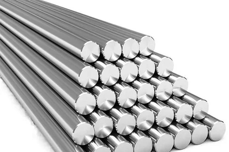
3.1 Benefits of high-grade steel and alloys
High-grade steels offer superior uniformity and hardness, which help minimize microscopic deformation during operation. When the raceways remain consistent under load, vibration tendencies diminish significantly. Premium alloys also resist fatigue better, giving the system more staying power.
3.2 Use of composite materials for damping
Composite materials add natural damping characteristics that metals alone can’t always provide. Their internal fiber structures dissipate vibrations rather than transmitting them directly to the bearing body. In demanding applications, these composites can feel like installing built-in shock absorbers.
3.3 Choosing materials based on application needs
High-speed or high-load environments demand materials with exceptional rigidity and fatigue resistance. Conversely, precision applications may benefit from materials that prioritize low noise and vibration absorption. Matching the material to real-world operating conditions prevents vibration headaches down the road.
4. Preload Optimization
4.1 Types of preload settings
Linear guides typically use light, medium, or heavy preload settings depending on the application. Each level influences rigidity and friction differently, affecting how the system responds to external forces. Selecting the right preload is a balancing act that requires both calculation and experience.
4.2 How incorrect preload increases vibration
Too little preload lets the balls chatter inside the raceway, creating a loose, rattling sensation. Too much preload can generate excessive friction and heat, which ironically leads to its own form of vibration. Incorrect preload is like tuning a guitar string too loose or too tight—neither will give you the sound you want.
4.3 Methods to fine-tune preload
Engineers often adjust preload step-by-step while monitoring resistance, vibration signatures, and motion smoothness. Precision shimming, alternate block selection, or swapping in preloaded units can help dial in the perfect amount. Taking a measured approach ensures the system hits that sweet spot between stiffness and smoothness.
5. Proper Rail and Block Alignment
5.1 Effects of misalignment on vibration
Misaligned rails twist and distort the load path, forcing the bearings into unnatural contact that sparks vibration instantly. Even tiny angular deviations can create cumulative resistance across the stroke. Alignment issues often snowball into noise, wear, and performance loss.
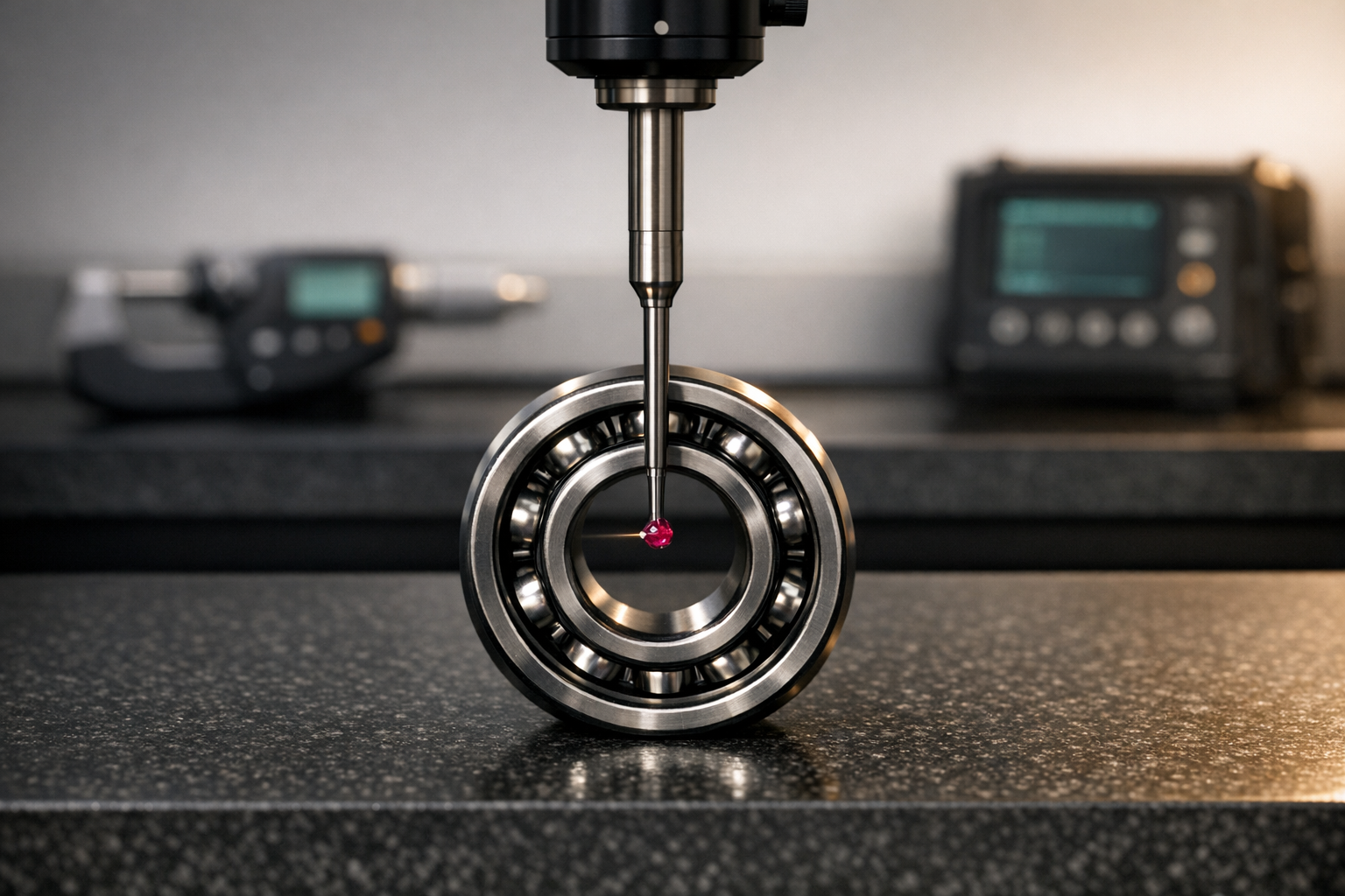
5.2 Tools for checking alignment
Dial indicators, laser alignment tools, and straightedges remain industry staples for diagnosing rail deviations. Modern systems even use digital inclinometers for ultra-precise readings. With the right tools, alignment errors stick out like a sore thumb.
5.3 Corrective techniques
Shimming, repositioning mounting surfaces, and tightening bolts in proper sequence help restore alignment harmony. Sometimes a full remount of the rail is the only reliable fix. Whatever the method, addressing alignment early prevents bigger mechanical woes later.
6. Lubrication Strategies
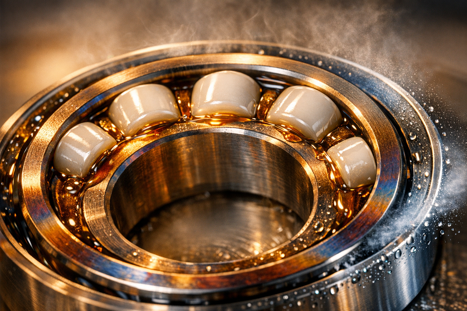
6.1 How lubrication minimizes friction-induced vibration
Proper lubrication forms a thin film that separates rolling elements from the raceways, drastically reducing friction and noise. Without that protective layer, metal-on-metal interaction generates vibration like a drum roll. Smooth lubrication transforms jittery movement into quiet, consistent motion.
6.2 Selecting the right lubricant type
Grease is ideal for general-purpose applications, while oils perform better in high-speed systems. Additives such as anti-wear agents or viscosity modifiers can further enhance vibration control. Matching lubricant chemistry to the job prevents surprises.
6.3 Establishing a lubrication schedule
Routine relubrication keeps contaminants at bay and maintains film integrity over time. Engineers should follow manufacturer recommendations but also adapt based on real-world duty cycles. A consistent schedule keeps the bearings running like a well-oiled machine—literally.
7. Surface Quality and Rail Straightness
7.1 Importance of smooth surface finishes
Smooth raceways reduce rolling resistance, allowing the balls to glide effortlessly without micro-bumping along the path. A rough surface magnifies vibration by introducing unpredictable microscopic impacts. High-quality surface finishes enhance both precision and longevity.
7.2 Identifying rail imperfections
Imperfections may appear as dents, scratches, waviness, or straightness deviations detectable through tactile inspection or measurement. High-resolution gauges can reveal inconsistencies invisible to the naked eye. Spotting these flaws early helps maintain consistent performance.
7.3 Surface treatment and correction methods
Grinding, polishing, and applying specialized coatings can rejuvenate damaged surfaces. In severe cases, replacing the rail may be the most economical long-term fix. Proper treatment restores the rolling interface to its original integrity.
8. Load Distribution and Capacity Matching
8.1 Impact of uneven loads
Uneven loading forces the bearing to operate off-center, causing erratic motion and amplified vibration. Heavy loads concentrated on one side lead to premature wear. Balanced loading ensures the system keeps its composure under stress.
8.2 Choosing the correct bearing size
Selecting a bearing too small for the load invites deflection and instability. Oversizing, however, adds unnecessary mass and may increase friction. The right size, calculated based on load and shock factors, keeps vibration in check.
8.3 Techniques for balanced load application
Using symmetrical mounting patterns, reinforcing structural components, and adjusting the center of gravity help distribute loads properly. Engineers often model load paths before installation to avoid surprises. Thoughtful preparation goes a long way.
9. Environmental Factors and Noise Sources
9.1 Temperature fluctuation effects
Temperature swings cause thermal expansion and contraction, subtly distorting rail geometry. These changes can alter preload, generate binding, and increase vibration. Maintaining stable temperatures helps the system stay calm and collected.
9.2 Contaminants that worsen vibration
Dust, chips, moisture, and chemical debris infiltrate bearings and create abrasive interactions. As contaminants accumulate, they turn smooth rolling into gritty chatter. Protecting the system from debris is non-negotiable.
9.3 Protecting bearings from harsh conditions
Bellows, covers, seals, and clean-room rated components help defend against environmental hazards. Strategic airflow control and filtration also minimize debris. These protective measures maintain the bearing’s integrity throughout its service life.
10. Installation Best Practices
10.1 Proper mounting procedures
Precision mounting ensures the rail sits on a stable and true foundation without distortions. Poor mounting introduces stresses that transmit directly into vibration. Careful workmanship during installation pays dividends.
10.2 Fastening techniques to reduce vibration
Tightening bolts in a cross-pattern helps evenly clamp the rails and prevent warping. Using torque-controlled tools ensures consistent fastening force. Stable fastening keeps the whole assembly rock solid.
10.3 Verification steps after installation
Post-installation checks include running the block through its full stroke, measuring resistance, and listening for abnormalities. Fine-tuning adjustments often follow initial testing. This verification ensures the system is ready to perform reliably.
11. Using Damping Components
11.1 Vibration-absorbing pads and mounts
Elastomeric pads help isolate the guide from machine-frame vibrations. They act like shock absorbers, soaking up unwanted oscillations. These pads offer an inexpensive yet effective vibration reduction solution.
11.2 Adding external dampers
External dampers provide controlled resistance that counteracts motion irregularities. They help stabilize fast-moving systems that frequently encounter dynamic loads. Many industries rely on these add-ons to enhance motion fidelity.
11.3 Integrating damping materials into machine frames
Embedding viscoelastic materials into the machine frame reduces resonance throughout the structure. These materials dissipate vibratory energy before it reaches the guides. Structural damping makes the entire system more resilient.
12. Motion Control and Drive System Optimization
12.1 How servo settings influence vibration
Aggressive servo tuning can cause overshooting, oscillation, and jitter in linear systems. Softer tuning parameters often tame unwanted vibrations. Fine adjustments create more predictable and stable movement.
12.2 Smoothing acceleration and deceleration
Gradual ramp-up and ramp-down motion profiles prevent shock loading. Smooth curves reduce mechanical strain and significantly damp vibration. It’s like easing onto the gas pedal instead of slamming it.
12.3 Reducing backlash in drive components
Backlash introduces sudden shifts in motion as mechanical play takes up slack. Eliminating or minimizing this play stabilizes the system’s response. Precision couplings and properly tensioned belts help keep things tight.
13. Maintenance Routines to Prevent Vibration
13.1 Inspection schedules
Regular inspections uncover wear patterns, lubrication lapses, and alignment drift before they escalate. Short, consistent checkups outperform long intervals between major service. These routines extend the system’s lifespan.
13.2 Replacing worn components
Once elements show signs of spalling, pitting, or deformation, replacement becomes unavoidable. Running worn components only accelerates vibration and system degradation. Swift replacement avoids costly downtime later.
13.3 Monitoring vibration trends
Vibration sensors or periodic vibration analysis help detect performance changes. When tracked over time, these patterns reveal developing issues. Proactive monitoring keeps the system ahead of trouble.
14. Common Mistakes That Cause Excess Vibration
14.1 Overloading the linear guide
Pushing a guide beyond its rated capacity forces it into a stress state it was never designed for. Overloading bends, binds, and ultimately destabilizes the system. Keeping within load limits protects precision.
14.2 Neglecting alignment checks
Skipping alignment checks is like ignoring a check-engine light—things might run for a while, but trouble is brewing. Misalignment silently amplifies vibration over time. Routine checks prevent this creeping issue.
14.3 Using incompatible components
Mixing mismatched rails, blocks, or drive elements introduces tolerance conflicts. These conflicts cause erratic rolling patterns and unnecessary motion noise. Compatibility ensures predictable behavior.
15. Application-Specific Vibration Reduction Tips
15.1 CNC machines and automation lines
CNC equipment requires high rigidity and low chatter to maintain accurate cuts. Using heavy preload, quality damping, and balanced spindle settings helps keep the toolpath steady. Even tiny vibrations can ruin a precision job.
15.2 Robotics and precision equipment
Robotic arms benefit from lightweight guides with excellent damping and smooth motion transitions. Reducing dynamic shock loads helps maintain consistent positioning accuracy. These machines thrive when vibration is tightly controlled.
15.3 Heavy-duty industrial systems
Industrial systems experience brute-force loads that demand heavy-duty bearings and reinforcements. Structural damping, oversized rail supports, and robust lubrication strategies keep vibration in check. These solutions maintain reliability in tough environments.
16. Future Innovations in Vibration Control
16.1 Smart bearings with embedded sensors
Embedded sensors allow bearings to self-report vibration levels, temperature changes, and load variations. This real-time data empowers quick adjustments. Smart technology keeps systems operating at peak performance.
16.2 Advanced damping materials
Next-generation polymers and hybrid composites promise unprecedented vibration absorption. These materials could dramatically quiet motion systems without sacrificing stiffness. Engineers are eager to leverage these breakthroughs.
16.3 Predictive maintenance technologies
Predictive algorithms analyze sensor data to flag issues before they escalate. This helps create maintenance schedules tailored to actual conditions instead of fixed intervals. It’s a smarter, more efficient way to keep machinery healthy.
17. Final Considerations
17.1 Evaluating system performance
Regular performance evaluations help confirm that vibration mitigation efforts are paying off. Engineers should track accuracy, noise levels, and wear patterns. Consistent evaluation ensures long-term stability.
17.2 Cost-benefit of vibration reduction methods
While some mitigation strategies carry upfront costs, they often pay for themselves in reduced downtime and extended component life. Careful comparison helps justify investment decisions. Long-term savings frequently outweigh short-term expenses.
17.3 Long-term reliability improvements
Reducing vibration enhances overall machine reliability and performance consistency. With fewer mechanical surprises, systems remain dependable even under demanding conditions. A stable, low-vibration setup keeps operations running smoothly for years to come.